CNC Gear Grinding Machines Guide: Designs, Grinding Processes, Accuracy and Key Components
CNC gear grinding machines are computer-controlled industrial machines used to improve the shape, surface finish, and dimensional accuracy of gears. CNC stands for Computer Numerical Control, a system that directs machine movements according to programmed instructions.
Context
CNC gear grinding machines are computer-controlled industrial machines used to improve the shape, surface finish, and dimensional accuracy of gears. CNC stands for Computer Numerical Control, a system that directs machine movements according to programmed instructions. These machines are commonly used in automotive manufacturing, aerospace production, industrial machinery, robotics, and other applications where gears must transmit motion and power with controlled accuracy.
Gear grinding developed from traditional mechanical grinding methods used to refine hardened metal components after machining and heat treatment. As manufacturing requirements became more demanding, computer-controlled systems made it possible to coordinate grinding wheel movements, workpiece rotation, and other machine operations with greater consistency. Modern CNC gear grinding machines combine mechanical components, electronic controls, precision measurement systems, and specialized software.
Understanding CNC Gear Grinding Machines
A gear contains teeth that engage with another gear or mechanical component to transfer rotational movement. Small variations in tooth shape, spacing, or surface condition can affect noise, vibration, wear, and power transmission. Gear grinding removes small amounts of material from gear teeth to correct selected geometric errors and improve their surface condition.
The process is often performed after gear cutting and heat treatment. Heat treatment increases hardness but can also cause dimensional changes. Grinding helps correct certain changes and brings the gear closer to its required specifications.
Common Machine Designs
CNC gear grinding machines are designed around different gear geometries and production requirements. Common designs include:
Generating gear grinders: Produce tooth profiles through coordinated movement between the grinding tool and the rotating gear. They are frequently used for external spur and helical gears.
Profile gear grinders: Use a grinding wheel shaped or dressed to match the intended tooth profile. They can be suitable for specific gear forms and precision requirements.
Worm-type grinding systems: Use a worm-shaped grinding wheel that engages with the gear through coordinated rotation. These systems are commonly associated with generating processes.
Internal gear grinders: Grind teeth located inside a ring-shaped gear, where tool access and machine geometry require specialized arrangements.
Bevel gear grinding machines: Process bevel gears, whose teeth are arranged on conical surfaces, using methods suited to their geometry.
The appropriate design depends on the gear type, tooth geometry, material, production volume, and required accuracy.
Importance
CNC gear grinding machines are important because gears are used in equipment that depends on controlled movement, reliable power transmission, and predictable mechanical performance. Examples include vehicle transmissions, aircraft drive systems, industrial gearboxes, wind turbine equipment, and automated production machinery.
Errors in gear geometry can produce uneven contact between teeth, unwanted vibration, increased noise, or premature wear. Grinding can correct certain profile and spacing errors that remain after earlier manufacturing operations. However, the final result also depends on the gear design, heat treatment, machine condition, tooling, and inspection process.
Key Components and Their Functions
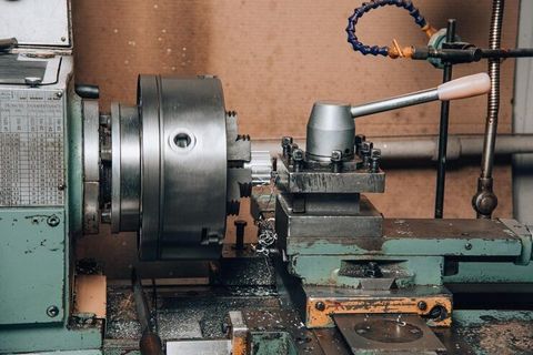
A CNC gear grinding machine contains several connected systems that control material removal and workpiece positioning.
Machine bed and frame: Support the machine structure and help maintain alignment during operation.
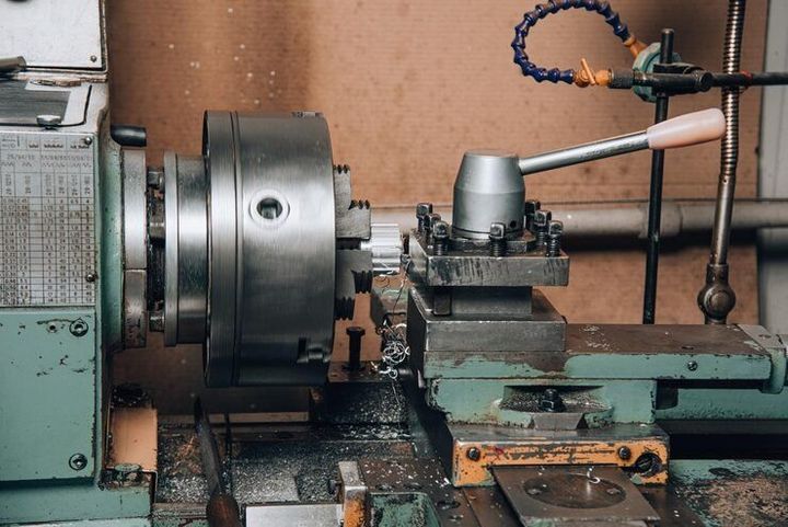
Workpiece spindle: Holds and rotates the gear during grinding.
Grinding spindle: Rotates the grinding wheel at the required operating speed.
Grinding wheel: Removes small amounts of material from the gear teeth through controlled contact.
CNC controller: Interprets programmed instructions and coordinates machine movements.
Servo motors and drive systems: Control the movement and rotation of machine axes.
Dressing unit: Restores the grinding wheel's intended shape and cutting condition.
Coolant system: Helps control heat, remove grinding debris, and manage the grinding environment.
Measurement equipment: Checks selected dimensions or tooth characteristics, depending on the machine configuration.
These components must operate together. A precise controller cannot fully compensate for a damaged wheel, poor workpiece mounting, thermal instability, or incorrect setup.
Accuracy and Surface Quality
Gear accuracy describes how closely a finished gear matches its specified dimensions and tooth geometry. Relevant characteristics include tooth profile, helix deviation, pitch variation, runout, and surface roughness. The importance of each characteristic depends on the gear's function and the applicable engineering specification.
Surface quality is also important because the tooth surfaces make contact as gears rotate. Grinding conditions, wheel condition, material properties, coolant delivery, and machine stability can affect the final finish. Excessive heat during grinding may damage the surface or alter material properties, making process control essential.
Comparing Gear Grinding Processes
| Process | Main operating principle | Common application |
|---|---|---|
| Generating grinding | Coordinated motion creates the tooth profile | External spur and helical gears |
| Profile grinding | Wheel follows a specified tooth contour | Specialized gear profiles |
| Internal gear grinding | Tool grinds teeth inside a gear | Internal ring gears |
| Bevel gear grinding | Grinding follows bevel gear geometry | Differential and angled drive systems |
The suitability of each process depends on gear geometry, tooling, machine capability, and the required production method. Not every machine can process every gear type.
Recent Updates
Developments in CNC gear grinding during 2024–2026 reflect wider manufacturing trends, including increased automation, digital monitoring, improved measurement integration, and more connected production systems. The specific capabilities available depend on the machine model, software, factory equipment, and production environment.
Automation and Digital Control
Modern systems may integrate automatic workpiece loading, tool management, dressing cycles, and programmed setup routines. These features can reduce manual handling and improve repeatability when properly configured. Automation does not remove the need for inspection, preventive maintenance, or trained operators.
Digital monitoring is also becoming more common in industrial manufacturing. Sensors and control software can track selected operating conditions, such as spindle behavior, vibration, temperature, and machine status. Depending on the system, this information can help identify unusual conditions before they cause larger production interruptions.
Measurement Integration and Manufacturing Data
Some CNC gear grinding systems incorporate in-process measurement or connections to external inspection equipment. These systems can help compare measured characteristics with programmed targets and identify deviations during production.
Manufacturers also use computer-aided design, computer-aided manufacturing, and simulation tools to prepare machining programs and examine process requirements. Data connections between machines and factory management systems can support production tracking and quality records. The degree of integration varies, and digital data still requires appropriate interpretation and validation.
Energy Use and Process Control
Grinding involves electrical power, coolant circulation, wheel rotation, and material removal. Manufacturers may focus on optimizing machine idle time, coolant management, wheel usage, and operating sequences to improve resource efficiency. Actual energy performance depends on the machine, workload, production schedule, and maintenance condition.
Laws or Policies
CNC gear grinding machines are influenced by industrial safety rules, machinery requirements, electrical standards, environmental controls, and workplace regulations. The applicable requirements depend on the country, the machine's intended use, and the facility where it operates.
Industrial Safety Requirements in India
In India, factories and industrial equipment may fall under applicable occupational safety, factory, electrical, and machinery-related requirements. The Occupational Safety, Health and Working Conditions Code, 2020, forms part of India's occupational safety legislation framework; its practical application depends on commencement notifications, applicable rules, and the relevant establishment.
Machine operators generally need suitable training in safe operation, workpiece clamping, grinding wheel handling, guarding, and emergency procedures. Protective enclosures, interlocks, emergency stops, and appropriate maintenance procedures help control risks associated with rotating equipment and grinding debris.
Quality and Technical Standards
International Organization for Standardization (ISO) standards provide technical frameworks relevant to gear geometry, accuracy assessment, and manufacturing quality. ISO 1328 includes accuracy classification for cylindrical gears, while other standards address gear measurement, terminology, and inspection methods. The applicable standard and edition depend on the gear type and specification.
Manufacturers may also use documented quality management procedures, including those aligned with ISO 9001, to manage production records, process controls, and corrective actions. Standards do not automatically establish that every machine or finished gear complies; conformity depends on the relevant requirements and verification process.
Environmental rules may also govern industrial waste, coolant disposal, noise, and energy use. Facilities should follow the applicable national, state, and local requirements.
Tools and Resources
Several technical tools help engineers, operators, and manufacturing teams understand CNC gear grinding requirements and assess finished components.
Design and Programming Software
Computer-aided design software helps create gear geometry and engineering drawings. Computer-aided manufacturing software can support machining strategies, tool paths, and CNC program preparation. Examples of industrial software environments include Siemens NX and other CAD/CAM platforms with suitable manufacturing capabilities.
Machine-specific programming software is also important because axis arrangements, wheel specifications, and available grinding cycles differ among machine models. Programs should be checked against the actual machine configuration before production.
Inspection and Measurement Equipment
Gear inspection may involve specialized gear measuring machines, coordinate measuring machines, profile measurement equipment, and surface roughness testers. These instruments measure different characteristics and may require specific fixtures, calibration, and operating procedures.
Useful inspection records can include:
Gear drawing and tolerance requirements.
Material and heat-treatment information.
Grinding wheel specifications and dressing records.
Tooth profile, lead, and pitch measurement results.
Surface finish results and machine maintenance records.
Technical references from ISO and the American Gear Manufacturers Association (AGMA) can help explain gear terminology, classification, and inspection practices. Machine manuals and wheel manufacturers' technical documentation provide additional information about operating limits and safe handling.
FAQs
What is a CNC gear grinding machine used for?
A CNC gear grinding machine refines gear teeth by removing small amounts of material under computer-controlled movement. It is used to improve specified geometric characteristics and surface finish, often after gear cutting and heat treatment.
What is the difference between generating and profile gear grinding?
Generating grinding creates tooth geometry through coordinated movement between the gear and grinding tool. Profile grinding follows a defined tooth contour using a suitably prepared grinding wheel. The appropriate process depends on the gear design and production requirements.
Which components affect CNC gear grinding accuracy?
Accuracy depends on the machine frame, workpiece and grinding spindles, CNC controller, drive systems, grinding wheel, dressing equipment, and measurement systems. Setup, temperature, vibration, and workpiece condition also influence results.
Which industries use CNC gear grinding machines?
Applications include automotive manufacturing, aerospace, industrial gearboxes, robotics, energy equipment, and precision machinery. The required gear geometry and accuracy vary according to the mechanical system.
How is gear grinding quality measured?
Quality assessment may include tooth profile deviation, helix deviation, pitch variation, runout, and surface roughness. Inspection methods and acceptance limits are selected according to the engineering drawing and applicable gear standards.
Conclusion
CNC gear grinding machines refine gear teeth through controlled grinding processes designed for different gear geometries. Their performance depends on machine design, component condition, tooling, programming, and accurate measurement. Automation and digital monitoring are expanding the ways manufacturers manage grinding operations, while safety rules and technical standards guide machine use and quality assessment. Understanding these factors provides a foundation for evaluating gear grinding processes and their role in modern manufacturing.

You May Also Like